How does common mode inductance affect the performance of power electronics systems?
In the world of power electronics, efficiency and reliability are paramount. One often-overlooked factor that can significantly influence these attributes is common mode inductance. While many engineers focus on input/output capacitance and switching frequency, the effects of common mode inductance can lead to unexpected performance issues.
Understanding Common Mode Inductance
Common mode inductance refers to the inductive coupling between the common mode signal and the ground or chassis of a power electronic system. In simpler terms, when signals in a circuit share a common return path, they can induce unwanted voltages that affect the system's performance. This phenomenon is particularly prevalent in high-frequency applications, such as inverters, converters, and motor drives, where rapid switching creates high-frequency noise.
Research has shown that common mode inductance can lead to increased electromagnetic interference (EMI), which can disrupt the operation of sensitive components. According to a study by the Institute of Electrical and Electronics Engineers (IEEE), systems with higher common mode inductance exhibited greater susceptibility to noise, resulting in a 30% drop in efficiency in some cases. This underscores the critical need for engineers to understand and manage common mode inductance in their designs.
Performance Issues Arising from Common Mode Inductance
The presence of common mode inductance can manifest in several ways, leading to performance degradation in power electronics systems. First, it can cause voltage spikes, leading to component stress and premature failure. For instance, capacitors and semiconductors are particularly vulnerable to these spikes, which can exceed their rated voltage limits.
Second, common mode inductance can contribute to inaccurate current sensing. Many power electronics systems rely on feedback loops for regulation and control. If common mode noise interferes with current sensing, it can lead to erroneous readings, causing the system to react incorrectly. This can lead to suboptimal performance, increased energy losses, and even system instability.
Lastly, common mode inductance can also result in increased conducted and radiated emissions, making systems non-compliant with regulatory standards such as CISPR 22 or FCC Part 15. Non-compliance not only poses a risk of penalties but can also lead to product recalls, damaging a company’s reputation.
Strategies to Mitigate Common Mode Inductance
Fortunately, engineers have several strategies at their disposal to mitigate the effects of common mode inductance. One effective method is to use differential signaling, which helps to cancel out common mode noise. This technique is widely used in communication systems and is increasingly being adopted in power electronics designs.
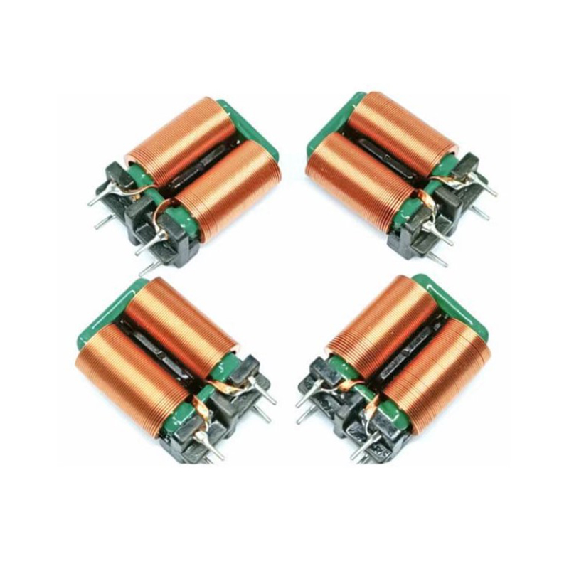
Another strategy is to employ common mode chokes. These inductive components are designed to filter out common mode noise while allowing differential signals to pass through. By integrating common mode chokes into the circuit, engineers can significantly reduce EMI and improve overall system performance.
Additionally, layout design plays a crucial role in managing common mode inductance. Keeping high-frequency paths short, using ground planes, and ensuring proper component placement can all help to minimize inductive coupling. Simulation tools can aid in visualizing and optimizing the layout to reduce unwanted inductance before the physical design is finalized.
Common mode inductance may not be the first thing that comes to mind when designing power electronics systems, but its impact is undeniable. From increased EMI to voltage spikes and inaccurate sensing, the consequences can be severe. By understanding the mechanisms at play and employing effective mitigation strategies, engineers can enhance the reliability and efficiency of their designs. As power electronics continue to evolve, addressing common mode inductance will be key to unlocking the full potential of these systems and ensuring compliance with industry standards.

 中文简体
中文简体